

Top ODM Surge Protective Device Factory: Reliable Manufacturing Solutions
2026-10-03
When lightning strikes or voltage spikes hit, your equipment’s survival often hinges on one overlooked component: the surge protective device. Not all factories are created equal, though. SINGI has built its reputation as a top ODM partner by pairing rigorous testing with flexible manufacturing, so you get reliable protection without the usual supply-chain guesswork. Curious how the right factory can turn a commodity part into a competitive advantage? Read on.
Why Custom ODM Designs Beat Generic Surge Protection
Generic surge protectors often rely on one-size-fits-all component choices and board layouts that leave performance gaps in demanding environments. A custom ODM design starts from the actual threat model of the device it protects—surge waveforms, operating voltage, physical space, and regulatory requirements—so every varistor, gas discharge tube, or TVS diode is sized and placed where it actually works in the circuit, not where it happens to fit on a shared template.
Another overlooked advantage is thermal behavior under repeated stress. Off-the-shelf protection often degrades silently because the heat dissipation path was never optimized for the enclosure or the expected transient frequency. With a custom design, the copper pours, component spacing, and sacrificial elements can be tuned to survive not just one big surge, but years of smaller spikes without drifting out of spec or taking down the main circuitry with them.
Custom designs also make economic sense once volume reaches a certain point. Instead of paying for overrated components that never see a worst-case surge in your product, or dealing with field failures from an undersized generic board, an ODM approach matches protection level to actual exposure. That reduces warranty costs, shrinks board footprint, and lets you integrate additional features like status monitoring or coordinated stage protection that generic modules simply don't allow.
The Assembly Line Details Most Factories Overlook
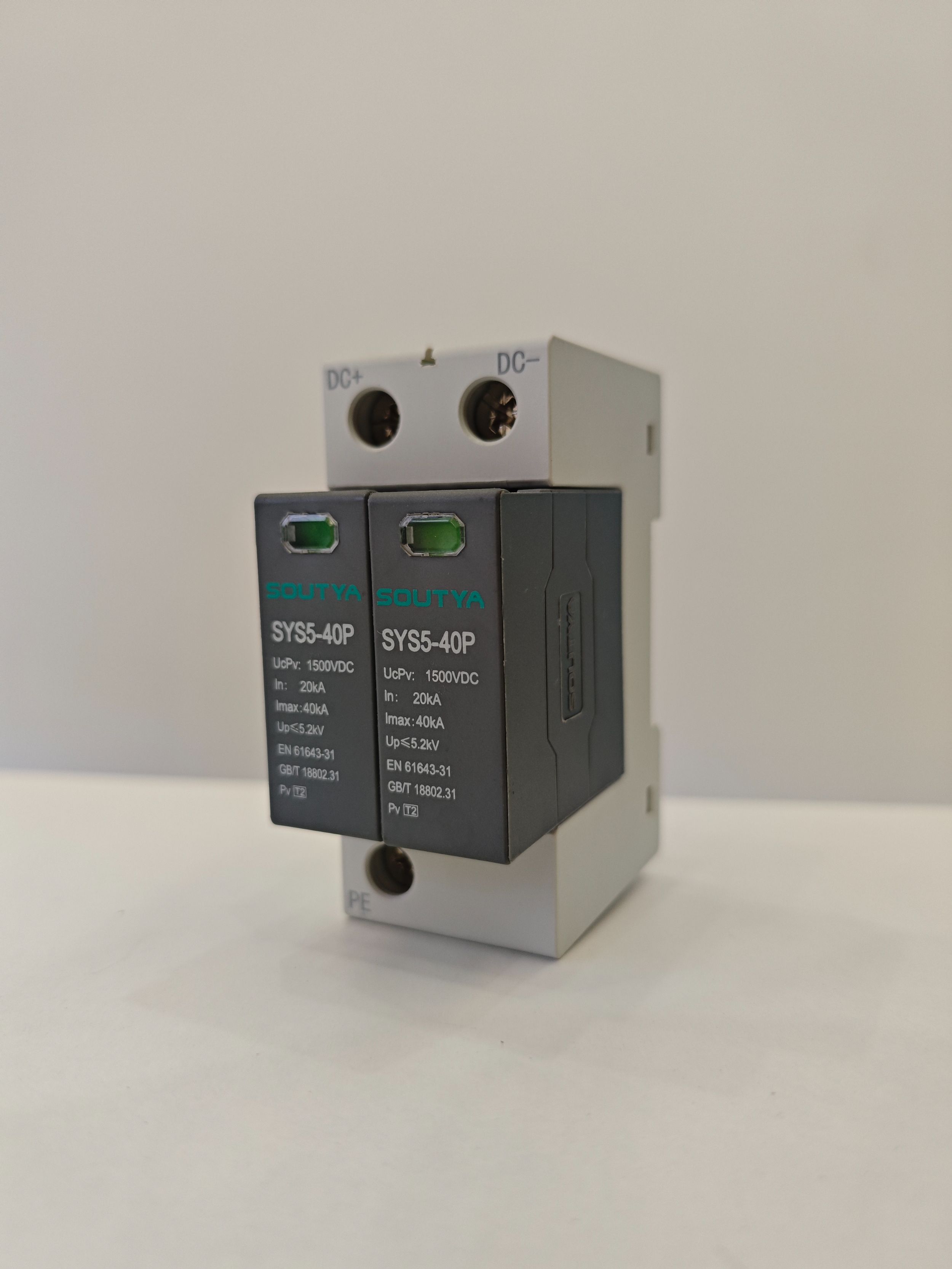
Walk the line at shift change and you'll spot the gaps: a torque wrench left at last week's setting because nobody rechecks calibration after lunch, worn fixture pins that let a bracket drift half a millimeter, a static charge building on a plastic housing no one thought to ground. These are not headline failures. They show up as intermittent defects, rework spikes on humid days, or a station that quietly slows down while everyone blames the new batch of parts.
Line balancing usually gets the attention, but the real yield killers hide in the spaces between stations. A shadow board missing one bit forces a six-minute search. Pneumatic pressure drops when the third shift starts and nobody adjusts the regulator. Light angle matters more than most engineers admit: a glare across a connector means a reversed terminal every few hundred units. Even the direction a label feeds into a printer can double the scrap rate if the liner peels the wrong way.
The fix is rarely expensive. Photograph each station at the same time every day and compare the small drifts. Mark tool settings with date stickers and audit them mid-run, not just at setup. Give operators a way to flag tiny annoyances without filling out a corrective action form. When those details get measured, they stop being invisible.
Material Selection: The Silent Factor in SPD Lifespan
Most surge protection devices rely on metal oxide varistors, but the choice of electrode plating and solder alloy quietly dictates how long the unit survives repeated clamping events. Cheaper silver flash coatings develop microcracks after thermal cycling, while nickel barrier layers with proper thickness maintain ohmic contact far longer. This isn't about branding; it's metallurgy that separates a five-year SPD from one that fails silently after two storm seasons.
Encapsulation compounds also matter more than spec sheets admit. A rigid epoxy that survives a bench test may crack when mounted on a vibrating panel near HVAC equipment, letting moisture reach the varistor edge. Softer polyurethane or silicone hybrids flex with thermal expansion mismatches between copper leads and ceramic bodies. The silent killer is rarely the surge itself—it's the gradual ingress that no LED indicator will ever report.
Even the PCB substrate contributes to aging. FR4 with high glass transition temperature resists carbonization during sustained overvoltage, while cheaper laminates become conductive paths for leakage current. Combine that with lead-free solder joints that grow tin whiskers under high humidity, and you have a device that no longer clamps, just smolders. Nobody notices until a downstream power supply quits for no apparent reason.
Simulating Real Faults: Testing Beyond the Datasheet
Datasheets provide a snapshot of guaranteed operating ranges and absolute maximum ratings, but they rarely capture the messy reality of a system under stress. A voltage rail that sags for 50 microseconds during a motor inrush, a ground bounce that lifts the reference plane by 300 mV, or a thermal gradient across a multi-die package can create conditions far outside the neat boundaries of a static table. Simulating real faults means building test scenarios from field returns, transient events, and corner-case interactions that never appear in a parametric table, yet are precisely what kills a board in production.
Instead of relying on single-parameter sweeps, fault simulation injects combinations that stress multiple domains at once. For example, a power sequencing fault might hold an I/O bank at 3.3 V while the core rail ramps from 0 to 1.1 V over an unusually long 200 ms window, creating a latch-up risk that no standalone ESD or overvoltage test would expose. Other realistic scenarios include ringing on a clock line that exceeds the absolute maximum for only two nanoseconds, repeated hot-plug events with a partially discharged bulk capacitor, and reverse current flow through a body diode during a brown-out. These are not hypothetical edge cases—they are the kind of failures that escape qualification because the initial test plan was built around the datasheet's clean limits.
The payoff of this approach is not just finding defects, but understanding failure mechanisms before they become warranty claims. Engineers who simulate real faults can tune protection circuits, adjust layout constraints, or add firmware guard bands based on measured weakness rather than assumed margin. Instead of asking "does this part meet its published specs," the question becomes "what happens when the system violates those specs in a plausible way—and can we still guarantee recovery?" That shift in perspective turns fault simulation from a validation afterthought into a design tool for building genuinely robust hardware.
Scaling Production Without Losing Component Traceability
Growing output volume often strains the systems that track individual parts. The temptation is to simplify processes by batching records or relying on paper tags, but that quickly erodes the ability to pinpoint a defect's origin. Instead, the most resilient manufacturers treat traceability as a design constraint, not an afterthought. They embed unique identifiers at the point of component creation—whether laser-etched codes, RFID inlays, or serialized labels—and ensure every subsequent step logs to that same thread.
As lines multiply, the real bottleneck shifts from marking parts to synchronizing data across stations, shifts, and even third-party suppliers. A practical approach is to keep the data model deliberately narrow: record only what changes hands, where, and when. This reduces the burden on operators while preserving a complete chain of custody. Automated scanners and vision systems can capture these events without slowing cycle time, but they are only useful if the underlying database rejects gaps rather than allowing silent skips.
Scaling also demands that traceability survive product variants and equipment upgrades. Using a stable identifier that never gets reused—even across years or product families—prevents ambiguity when old records are audited. Some teams adopt a simple rule: if a component can be separated from its parent assembly, it gets its own lineage. This granularity costs little at high volumes but becomes invaluable during recalls, warranty analysis, or regulatory inspections, where the ability to trace one unit back through every handoff is what keeps a production ramp from turning into a liability.
Engineering Collaboration That Starts With Your Schematic
Schematic tools have always promised a single source of truth, but most teams know the reality: the schematic lives in one window while conversations about it scatter across email, chat, and meeting notes. That disconnect turns every design review into an archaeology project. When your schematic itself becomes the workspace where pins are questioned, trade-offs are debated, and decisions get recorded, the distance between idea and implementation shrinks.
Instead of exporting static PDFs and waiting for markups, engineers can drop comments directly on a net, a component, or a block. Those notes stay anchored to the exact revision they refer to, so no one wastes time wondering if a concern was already resolved or if it applies to an older spin. The result is less cross-referencing and more actual engineering.
Collaboration that starts in the schematic also changes who gets invited into the conversation. Firmware, layout, and test engineers can see the reasoning behind a pull-up value or a filter topology without asking for a summary. That visibility catches mistakes earlier because the context is already attached to the design, not buried in a thread someone forgot to forward.
FAQ
We build AC and DC surge protectors across Type 1, Type 2, and Type 3 categories, including DIN-rail modules, plug-in cartridges, and PCB-mounted variants. Custom voltage ratings, pole counts, and remote signaling contacts are all part of the standard ODM scope.
It starts with a shared product specification and a DFM review. Then we prototype the enclosure and PCB, run pre-compliance tests at our in-house lab, and only move to tooling once the client approves samples. Pilot runs include full traceability before scaling up.
Yes. We offer private tooling for housings, custom color compounding, laser marking, and silkscreen printing. For lower-volume projects, we can use shared molds with client-specific front plates and packaging.
Most designs are prepared for IEC 61643-11 and UL 1449. We also support CE, CB, and TUV mark testing. Our documentation package includes full test reports, Bill of Materials, and component certificates to simplify the client's certification process.
We buy MOVs, GDTs, and thermal fuses only from approved vendor lists, then run incoming inspection on every batch. For critical parts, we lock the supplier and version in the BOM, so production units match the certified samples.
For orders using existing molds, production typically takes 4 to 6 weeks. If new plastic tooling is needed, add another 3 to 5 weeks for mold design and trials. Rush schedules are possible when the client provides clear specifications early.
Every surge protector passes a 100% electrical safety test, including high-voltage withstand, leakage current, and thermal disconnection checks. We also pull random samples from each batch for 8/20 µs surge impulse testing and load cycling.
Yes. The same engineers who develop the product stay involved after delivery. We help with field failure analysis, firmware or component changes, certification updates, and cost-reduction redesigns without changing performance.
Conclusion
A surge protective device is only as dependable as the thinking behind its design. Generic off-the-shelf protection rarely accounts for the specific fault currents, voltage transients, or physical layout your equipment will actually face. A top ODM factory starts from your requirements, not a catalog. Custom designs allow for precise coordination between stage-one and stage-two suppression, avoiding the gaps that off-the-shelf units leave open. On the assembly line, small details matter more than most realize: torque settings on terminal screws, conformal coating thickness, even the orientation of a varistor can change clamping performance under stress. Material selection is another quiet contributor to lifespan. Metal oxide varistors with tighter voltage tolerances, thermally protected enclosures, and high-grade PCB substrates all determine whether an SPD will shrug off years of transients or fail early.
Testing separates a reliable ODM partner from a simple assembler. The best factories simulate real fault conditions—repeated 8/20 µs surges, temporary overvoltages, and combined wave events—rather than only checking datasheet curves. This reveals weaknesses like thermal runaway or poor coordination that standard pass/fail tests miss. Scaling production is where traceability becomes critical. Every batch of varistors, every solder paste lot, and every assembly operator should be linked to the final serial number. Without that, a field failure is nearly impossible to investigate. Finally, engineering collaboration should begin with your schematic, not end after a quote. A factory that asks about your grounding scheme, cable lengths, and protection levels can adjust the SPD design before tooling starts, saving weeks of redesign later. That level of involvement is what turns a manufacturing vendor into a genuine reliability partner.
Contact Us
Contact Person: Jack
Email: [email protected]
Tel/WhatsApp: (+86) 13757759651
Website: https://www.singi.com