

Why Does Pressure Compensation Matter When Selecting a UV Ozone Analyzer?
2026-11-16
1. Why Can a UV Ozone Analyze Unit Read Correctly in the Lab but Drift in a Pressurized Process?
A water treatment plant installs an Ozone Analyze unit on a pressurized ozone contactor. The unit is calibrated in our factory at atmospheric pressure and passes the bench test. After installation, the reading is 18 percent higher than the lab reference. The plant team checks the lamp, the flow, and the calibration gas, and finds no fault. Beijing Zetron Technology Co., Ltd. reviews the installation data and identifies the cause: the sample pressure at the cell is 120 kPa absolute, while the calibration was performed at 101 kPa absolute.
The error is not a sensor failure. It is a pressure compensation gap. Our engineers see the same pattern in many commissioning reports: the analyzer is accurate at the calibration pressure and drifts when the process pressure changes. The drift is predictable, which means it can be corrected in the instrument if the pressure is known.
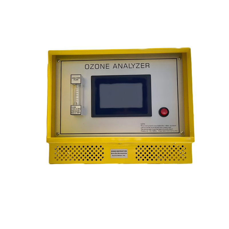
2. How Does Pressure Change the UV Absorption Reading Inside the Measurement Cell?
In our factory, a UV Ozone Analyze system measures absorbance at 254 nm and converts it to concentration using the Beer-Lambert relationship. The absorbance depends on the number of ozone molecules in the light path, and the number of molecules per unit volume depends on pressure and temperature. When the sample gas is compressed, more molecules occupy the same cell volume, and the absorbance rises even if the ozone mass fraction is unchanged.
Without compensation, the reported concentration scales roughly with the absolute pressure ratio. A reading that is correct at 101 kPa can be 20 percent high at 120 kPa and 50 percent high at 150 kPa. Our calibration procedure therefore records the cell pressure at the moment of calibration and applies a correction whenever the sample pressure differs. The correction is a multiplication by the ratio of the calibration pressure to the actual pressure, with a temperature term added when the cell temperature is not controlled.
| Sample pressure, kPa abs | True concentration, g per Nm3 | Uncompensated reading, g per Nm3 | Error, percent | Compensated reading, g per Nm3 |
| 80 | 50 | 39.5 | -21.0 | 50 |
| 100 | 50 | 49.4 | -1.2 | 50 |
| 120 | 50 | 59.2 | 18.4 | 50 |
| 150 | 50 | 74.0 | 48.0 | 50 |
| 200 | 50 | 98.7 | 97.4 | 50 |
The table shows why a fixed calibration factor is not enough for a pressurized process. The uncompensated reading tracks the pressure ratio, while the compensated reading stays close to the true value. An Ozone Analyze unit that lacks pressure input cannot distinguish a real concentration change from a pressure change, and the operator may adjust the ozone generator in the wrong direction.
3. What Compensation Methods Are Available, and Which One Fits a Given Installation?
There are four practical compensation methods. The first is manual entry of a fixed line pressure. The second is an external pressure transmitter connected to the analyzer. The third is an internal absolute pressure sensor at the measurement cell. The fourth is a combination of pressure regulation and flow control that holds the cell at a constant pressure. Beijing Zetron Technology Co., Ltd. supplies analyzers with the internal sensor as standard and with the external input as an option. Our production team configures the compensation range to match the sample pressure at the tap.
| Compensation method | Pressure input | Typical accuracy | Installation requirement | Best suited to |
| Manual fixed pressure | Operator entry | plus or minus 3 to 5 percent if pressure is stable | No sensor, stable process pressure | Labs and constant pressure skids |
| External pressure transmitter | 4 to 20 mA or RS485 | plus or minus 1 to 2 percent of reading | Transmitter at sample tap, scaled input | Processes with varying pressure |
| Internal absolute pressure sensor | Built in at cell | plus or minus 1 percent of full scale | Factory calibrated, no external wiring | Compact analyzers and OEM skids |
| Pressure regulation and flow control | Regulated cell pressure | plus or minus 0.5 to 1 percent with stable flow | Regulator and flow controller | High accuracy compliance monitoring |
| No compensation | Assumes atmospheric | plus or minus 10 to 50 percent depending on pressure | None | Open atmospheric monitoring only |
The choice depends on the pressure stability and the accuracy target. A stable skid with a known pressure can use manual entry, but a process with varying pressure needs a live input. Our service team checks the pressure tap location, the transmitter range, and the analyzer input scaling before commissioning. The standard Ozone Analyze configuration includes a range of 0 to 200 grams per normal cubic meter, a resolution of 0.1 gram per normal cubic meter, an accuracy of plus or minus 1 percent of full scale, a pressure compensation range of 50 to 200 kPa absolute, a temperature compensation range of 0 to 50 degrees C, a response time below 5 seconds, a sample flow of 0.5 to 2 liters per minute, a 4 to 20 mA output, an RS485 port, and two alarm relays. A unit with a built-in sensor reduces wiring but must be calibrated at the same pressure reference as the transmitter.
4. Why Do Sample Conditioning and Sensor Placement Decide Whether Compensation Works?
Sample conditioning decides whether the compensation is meaningful. The pressure must be measured at the same point where the ozone concentration is measured, not upstream of a regulator or downstream of a long sample line. A regulator that drops the pressure to the cell also changes the concentration reading, and the compensation must account for the regulated pressure, not the line pressure. Our installation guide requires a pressure tap within 300 mm of the cell and a sample flow between 0.5 and 2 liters per minute.
Temperature also affects the reading, and pressure compensation without temperature compensation is incomplete. The analyzer should correct both variables or should hold the cell at a controlled temperature. Beijing Zetron Technology Co., Ltd. tests each Ozone Analyze unit at three pressures and three temperatures before shipment, and records the correction curve in the calibration file. Our factory keeps the test record with the serial number so that a field question can be checked against the original data.
5. How Should Buyers Specify and Verify Pressure Compensation in an Ozone Analyze Purchase?
The purchase specification should list the compensation method, the pressure range, the pressure input signal, the accuracy at the specified range, and the calibration reference pressure. It should also state the sample flow, the temperature range, and the output signal. Our team reviews the specification against the installation drawing before the order is released, and flags any mismatch between the pressure tap and the analyzer input.
Verification should include a bench test at three pressures, a zero and span check, and a comparison with a reference analyzer at the actual sample pressure. An Ozone Analyze unit that passes the bench test but fails the pressure test should not be accepted. Our engineers witness the factory acceptance test and provide the signed test report with the shipment.
Frequently Asked Questions About Pressure Compensation
Summary and next step. Pressure compensation matters because a UV ozone analyzer measures molecules in a fixed cell volume, and pressure changes that volume density. Without compensation, the reading can be high or low by tens of percent, and the operator may adjust the ozone generator in the wrong direction. The compensation method should match the pressure stability, the accuracy target, and the sample conditioning. The purchase specification should include the pressure range, the input signal, the calibration reference, and the verification test. A factory acceptance test at three pressures and a signed test report close the loop.